Sunday, 21 July 2019

ROUTER BASICS


Router Basics : Mode and Interfaces.


There are two types of components in router .

1. external components:

(a).  serial port:- Router to router connectivity.

(b).External port:_- lan connectivity.

(c). AUI:- Additional lan port.

(d). AUX:- Wan connectivity through modem.

(e). Consol port:- To confiqure the router/switch from another computer.

Internal component;-

(a). Motherboard:- Gives a plateform to connect all device.

(b). ROM:- it is stand for Read Only Memory .it is used to read and write data.

(c). RAM:- It is a volatile memory .it hold only active configuration & running configuration of router. it  hold routing table & Arp table.

(d). NV-RAM:- It is non-volatile memory,which is startup configuration.

Flash Memory:- It conten's IOS of router.

Mini IOS:- it provides to installed IOS of router,whome IOS is not present in flash memory.

configuration resister value in router:-

It is 16 bit value which is represented in hexadecimal formate that fells the router form whoes it will boot.
there are four types of resister value.

(1). 0x2100 tell the router to boot from rom monitor mode (safe mode).

 (2). 0x2101:- To boot from mini ios.

(3). 0x2102:- to boot from flash with nvram/startup confiquration. it is default configuration resister value.

(4). 0x2142:- Boot from flash ,but ignore nvram configuration.
Flow chart of Router/Boot sequence :
1. POST.:
 2. Boot Strap:
 3. Flash:
4. NVRAM:
5.RAM:

VLSM(Variable Length Subnet Mask )

 Variable Length Subnet Mask :

                                                     Neither RIPv1 nor IGRP routing protocols have a field for subnet information, so the subnet information gets dropped. What this means is that if a router running RIP has a subnet mask of a certain value, it assumes that all interfaces within the classful address space have the same subnet mask. This is called classful routing, and RIP and IGRP are both considered classful routing protocols. Classless routing protocols, however, do support the advertisement of subnet information. Therefore, you can use VLSM with routing protocols such as RIPv2, EIGRP, and OSPF. The benefit of this type of network is that you save a bunch of IP address space with it.


 VLSM  enables you to have more than one mask for a given class of address, albeit a class A, B, or C network number.

VLSM, originally defined in RFC 1812, allows you to apply different subnet masks to the same class address space Classful protocols, such as RIPv1 and IGRP, do not support VLSM. To deploy VLSM requires a routing protocol that is classless—BGP, EIGRP, IS-IS, OSPF, or RIPv2, for instance. VLSM provides Two major advantages.
   .more efficient use of addressing .

2.      Ability to perform route summarization when you perform classfulsubnetting, all subnets have the same number of hosts because they all use the same subnet mask. This leads to inefficiencies. For example, if you borrow 4 bits on a Class C network, you end up with 14 valid subnets of 14 valid hosts. A serial link to another router only needs 2 hosts, but with classical subnetting, you end up wasting 12 of those hosts. Even with the ability to use NAT and private addresses, where you should never run out of addresses in a network design, you still want to ensure that the IP plan that you create is as efficient as possible. An efficient addressing scheme using VLSM.

3. Find the largest segment in the area—the segment with the largest number of devices connected to it.

4. Find the appropriate subnet mask for the largest network segment.

5.  Write down your subnet numbers to fit your subnet mask.

6. For your smaller segments, take one of these newly created subnets and apply a different, more appropriate, subnet mask to it.
7. Write down your newly subnetted subnets.

8. For even smaller segments, go back to step 4.
  • Route Summarization :


    Route summarization is the ability to take a bunch of contiguous network numbers in your routing table and advertise these contiguous routes as a single summarized route. Route summarization, or supernetting, is needed to reduce the number of routes that a router advertises to its neighbor. Remember that for every route you advertise, the size of your update grows. It has been said that if there were no route summarization, the Internet backbone would have warped from the total size of its own routing tables back in 1997. Routing updates, whether done with a distance vector or link-state protocol, grow with the number of routes you need to advertise. In simple terms, a router that needs to advertise ten routes needs ten specific lines in its update packet. The more routes you have to advertise, the bigger the packet. Thebigger the packet, the more bandwidth the update takes, reducing the bandwidth available to transfer data. But with route summarization, you can advertise many routes with only one line in an update packet. This reduces the size of the update, allowing you more bandwidth for data transfer. Summarization allows you to create a more efficient routing environment by providing the following advantages:
    1. It reduces the size of routing tables, requiring less memory and processing.
    2. It reduces the size of updates, requiring less bandwidth.
    3. It contains network problems 
     Example of VLSM  :

     
  • SEGMENT,FRAME AND PACKET


    What is a Frame?


    Frame is the name used to represent the Protocol Data Unit(PDU) at one of the lowest level in the reference model. Its the PDU at data link layer. Any communication between two computers or two networking devices is always done using MAC addresses. MAC addresses are nothing but physical addresses associated with the network interface card.

    If you want to deliver a message to another machine on a network, it will first search for the physical address of the destination. There is actually something called as ARP, that does the job of translating IP addresses to Physical addresses. ARP(address resolution protocol) is one of the core components in networking.

  •  Every operating system with networking capability, has this feature called ARP. It does the job of maintaining a mapping between ip addresses and corresponding MAC addresses(Physical address).

  • PDU of Transport layer is called as a “Segment”, PDU of network layer is called as a “Packet” & PDU of data link layer is called as a “Frame”.


  • What is segment:?


    So applications provide byte stream to TCP, and TCP takes care of creating it into discrete pieces of messages. These discrete pieces of messages at Transport Layer(where TCP comes into picture) are called "Segments".

    What is packets?

    The Segment (which includes data chunk and its headers) are then passed down from Transport layer to the next layer called Network Layer. Here is where IP addresses steps in. I think out of all three(Segments, Packets & Frames), packets are something that's mostly correctly used in different places. As packets are discrete messages in Network Layer which has IP addresses, they are sometimes referred to as "IP packets".


    NOTE:-  A "segment" which is now sitting inside a "packet", is now passed down to the next layer called data link layer. Data link layer will add its own control and functional fields on top of the packet(called headers) to make something called as a "frame".
     
     
    SEGMENT Packet frame
    PDU at transport layer. PDU at network layer. PDU at Data-link layer.
    Port numbers are part of Segments IP addresses are part of a Packet Mac addresses are part of Frames
     

    TCP/IP

    TCP/IP(Transmission Control Protocol/Internet Protocol): 
                                                                                                        IT  is a suite of communication protocols used to interconnect network devices on the internet. TCP/IP can also be used as a communications protocol in a private network (an intranet or an extranet).
    The entire internet protocol suite -- a set of rules and procedures.

    The history of TCP/IP:

    The Defense Advanced Research Projects Agency (DARPA), the research branch of the U.S. Department of Defense, created the TCP/IP model in the 1970s for use in ARPANET, a wide area network that preceded the internet. TCP/IP was originally designed for the Unix operating system, and it has been built into all of the operating systems that came after it.
    The TCP/IP model and its related protocols are now maintained by the Internet Engineering Task Force.


    How TCP/IP works:

    TCP/IP uses the client/server model of communication in which a user or machine (a client) is provided a service (like sending a webpage) by another computer (a server) in the network.
    Collectively, the TCP/IP suite of protocols is classified as stateless, which means each client request is considered new because it is unrelated to previous requests. Being stateless frees up network paths so they can be used continuously.
    The transport layer itself, however, is stateful. It transmits a single message, and its connection remains in place until all the packets in a message have been received and reassembled at the destination.

    TCP/IP model layers

    TCP/IP functionality is divided into four layers, each of which include specific protocols.
    • The application layer provides applications with standardized data exchange. Its protocols include the Hypertext Transfer Protocol (HTTP), File Transfer Protocol (FTP), Post Office Protocol 3 (POP3), Simple Mail Transfer Protocol (SMTP) and Simple Network Management Protocol (SNMP).
    • The transport layer is responsible for maintaining end-to-end communications across the network. TCP handles communications between hosts and provides flow control, multiplexing and reliability. The transport protocols include TCP and User Datagram Protocol (UDP), which is sometimes used instead of TCP for special purposes.
    • The network layer, also called the internet layer, deals with packets and connects independent networks to transport the packets across network boundaries. The network layer protocols are the IP and the Internet Control Message Protocol (ICMP), which is used for error reporting.
    • The physical layer consists of protocols that operate only on a link -- the network component that interconnects nodes or hosts in the network. The protocols in this layer include Ethernet for local area networks (LANs) and the Address Resolution Protocol (ARP).

    Advantages of TCP/IP:

    TCP/IP is nonproprietary and, as a result, is not controlled by any single company. Therefore, the internet protocol suite can be modified easily. It is compatible with all operating systems, so it can communicate with any other system. The internet protocol suite is also compatible with all types of computer hardware and networks.

    Saturday, 20 July 2019

    OSI Models

     OSI Is Stand for Open System Interconnection. the OSI Models defines a networking for implanting protocol in seven layers by the     international organisation for standard(iSO) .the oSI reference model is based on protoco develop by iSO so the model is also called ISO OSI reference model.
     It was develop in  1984 .it has seven layer.there are following seven layer.


    7.  application layer.  

    6. presentation layer.  

    5. Session layer.  

    4, transport layer.  

    3.Network layer.

    2.Datalink layer.

    1.Physical layer.

    vv

     Benefite and reason.


    1.  To divide the interrelated aspects of network operation into less complex operations.
    2.  To define standard interfaces to achieve compatibility and multivendor integration.
     
    3. To achieve a modular approach to networking protocols so new applications and services can be deployed   without redesigning other layers.
     4. To keep changes in one area from affecting other layers.
     
    5. To ease troubleshooting using data packets which will have specific information about each layer.


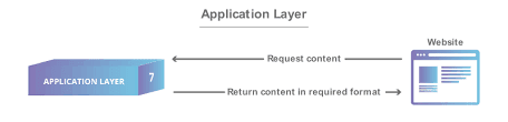
    Application layer /layer7

      1. the application layer is top  most layer in osi model.also known as layer 7.
    2. by thi layer user communicate to the computer server.the application used in communication is email,chrome,skype etc.
    3. Provides interface between OSI RM and end user applications
    4. Provides network services to user client/server-based applications
    5, Establishes and defines program-to-program communication
  •       6. Identifies availability of intended communication partner
  •       Examples  include ftp, tftp, http, www browsers, DNS, SMTP, telnet .


  • Presentation layer/layer6.


    1.  Defines data format for transmission .
     2. Ensures arriving data from the network can be used by the application and information sent by the application can be transmitted on the network .
    3.  Performs encryption and decryption .
     Example:   representations include ASCII, EBCDIC, JPEG, TIFF, PICT, MPEG, MIDI, HTML.

    Session layer/layer 5.


    1. Session layer is a layer5 that controls /manage mainly session time of website/networks.
     2. Defines how to start, control and end sessions
     3. RPCs operate at this layer Logon Validation happens at this layer.
     4. Named Pipes defined at this layer – Named Pipes use TCP to guarantee communications, example – NetLogon 5.  Session layer organizes communication through simplex, halfduplex or full-duplex
    Example:    protocols include SQL, RPC, NetBIOS, Named Pipes .

    Transport layer/layer 4

    .
    1. It is a main types of layers in OSI Model because it's functions works is provide data dealing mechanism between the application in the networks.
    2.   Segments data to be passed down to the Network layer and reassembles data for the Session and upper layers 3.    Provides the choice of connection-oriented and guaranteed (TCP) or connectionless and non-guaranteed (UDP) delivery of data
     4.    Provides end-to-end transport services
     5.  Provides flow control to overcome congestion in the receiving host’s buffers
    6.  TCP uses port numbers to multiplex from the Transport layer through to the Application layer
    [multiplex = ability to send different data from a number of applications in the same transport connection]           7.  3 flow control mechanisms

    Network layer/layer 3.

     
    1. It is responsible for communication network.it recognise network with help of networks address.Network address is logical address like IP Address IPX.it is a commmon for a computer .
    2. The determination or routing is performed at this layer.Router is worked on this layer.
    3. Network layer maintains routing table .

    Data-link layer/layer 2.

    1. Provides error-free link between 2 devices – CRC used for error checking .
     2. Packets from the Network layer are placed into frames .
    3. Data Link layer handles physical transmission of data from one node to another
     4. Handles error notification
    5. IEEE subdivided this layer into 2 sublayers

    Physical layer/layer 1.

     
    1.Defines connections – RJ-45, RJ-11, BNC, HSSI, RS-232
    2.Places frames, represented as bits, onto media as electric signals or pulses of light
    3.  Hubs and repeaters operate at this layer .


    MAC(Media Access Control) Address: AND ARP

     MAC(Media Access Control) Address:

    • MAC stand for Media Access Control.
    • it is a physical address/ethernet hardware address /Hardware address.
    • it works on data link layer/layer 2.
    • it is 48 bits device.
    • Reprented in hexadecimal formate.
    • It has 12 digit,each and every digit contains 4 bits,
    • the MAC address is as llike as 1234:3ab:fd23 or 12-14-222-ab-fd-22.
    • The first MAC address is 0000:0000:0000 ,that is also called as unknown MAC address.
    • The last MAC address is ffff:ffff:ffff ,this is also called as broadcast MAC address.
    • MAC adddress is assign by vender/manufactured company but it conyrolled by IANA.
    • firt 24 bits /6 digit for vender id & last 24 bit represent uniquic id.
    • It is burn or assign in NIC.
    • NIC is stand for network interface card.
    •  

    ARP(ADDRESS Resolution Protocol):
     
    • ARP is used to map an internet protocol address to a physical machin address of a computer
    • An ip assign for 32 bits long, but mac address of network caid is 48 bits large ,hence ARP is the protocol which match the ip address yo yje mac address of the computer.
    • To check ARP table use commond arp-a.
    • Dynamic:- the dynamic arp entries are entered the client makes an arp request but can not be satisfied by entries already presented in the ARP table.
    • Static:-  static arp entries rhat have been entered manualy using the ARP utility.it does not actually part it self.

    What is IP, Subnet-Mask ,Subnetting and CIDR


    What is IP(internet protocol) :


    An Internet Protocol address (IP address) is a numerical label assigned to each device connected to a computer network that uses the Internet Protocol for communication. An IP address serves two principal functions: host or network interface identification and location addressing.
    IPv4:-  

    Internet Protocol version 4 (IPv4) defines an IP address as a 32-bit number.[2] However, because of the growth of the Internet and the depletion of available IPv4 addresses, a new version of IP (IPv6), using 128 bits for the IP address, was developed in 1995,[3] and standardized in December 1998.[4] In July 2017, a final definition of the protocol was published.[5] IPv6 deployment has been ongoing since the mid-2000s.

     IP addresses are usually written and displayed in human-readable notations, such as 172.16.254.1 in IPv4, and 2001:db8:0:1234:0:567:8:1 in IPv6. The size of the routing prefix of the address is designated in CIDR notation by suffixing the address with the number of significant bits, e.g., 192.168.1.15/24, which is equivalent to the historically used subnet mask 255.255.255.0

    The IP address space is managed globally by the Internet Assigned Numbers Authority (IANA), and by five regional Internet registries (RIRs) responsible in their designated territories for assignment to end users and local Internet registries, such as Internet service providers. IPv4 addresses have been distributed by IANA to the RIRs in blocks of approximately 16.8 million addresses each. Each ISP or private network administrator assigns an IP address to each device connected to its network. Such assignments may be on a static (fixed or permanent) or dynamic basis, depending on its software and practices.

    Function:-

    An IP address serves two principal functions. It identifies the host, or more specifically its network interface, and it provides the location of the host in the network, and thus the capability of establishing a path to that host. Its role has been characterized as follows: "A name indicates what we seek. An address indicates where it is. A route indicates how to get there."[2] The header of each IP packet contains the IP address of the sending host, and that of the destination host.

     SUBNETTING:-

                                          The subnetting is used for to redused amount of wasting ip address.in networking , lets take a example that is we need 20 ip address then we will take a network there is 32 ip address then our 12 ip is waiste  .so the networking team found a solution of saving ip address that is subnetting ,not all waisted of ip sve but more of them can save now.


     Benefit of Subnetting :   
                                             

    Reduced network trafic:-          One network will not access the data of other network without the use of router. Thus we can reduce the amount of data remain in one network. Less data less overhead, collision, or broadcast storm.


    Simplified management :-     It's easier to identify and isolate network problems in a group of Smaller connected networks than within one gigantic network. Facilitated spanning of large geographical distances Because WAN links are significantly slower and more expensive than LAN links, a single large network that spans long distances can create problems in every area earlier listed. Connecting multiple smaller networks makes the system more efficient.

     
     Subnet mask :
                                 A subnet mask is a 32-bit value that allows the receiver of IP packets to distinguish the network ID portion of the IP address from the host ID portion of the IP address. Every IP address is composed of a network component and a host component. The subnet mask has a single purpose: to identify which part of an IP address is the network component and which part is the host component. Subnet mask value 0 represent host ID while subnet mask value     1 to 255 represents Network ID in ip address.
  • NOTE:-We can also say that subnet mask is used to define the no. of host bit and no. of  network bit in network ip.
  •  
     Classless Inter-Domain Routing (CIDR) :
                                                                                                                                            This slash          ( / ) notation is sometimes called CIDR (Classless Inter-Domain Routing) notation. It's basically the method that ISPs (Internet service providers) use to allocate a number of Addresses to a company, a home—a customer. The slash notation is simply the number of 1s in a row in the subnet mask. The real reason to use CIDR notation is simply that it is easier to say and especially to type.
     
    Block Size :
    The process of subnetting creates several smaller classless subnets out of one larger classful . The spacing between these subnets, or how many IP addresses apart they are, is called the Block Size.

  • Network ID and Broadcast ID :
                                                                            The first address in a network number is called the network address, or wire number. This address is used to uniquely identify one segment or broadcast domain from all the other segments in the network.

    The Broadcast ID :     
                                           The last address in the network number is called the directed broadcast address and is used to represent all hosts on this network segment. it is the common address of all hosts on that Network ID. This should not be confused with a full IP broadcast to the address of 255.255.255.255, which hits every IP host that can hear it; the Broadcast ID hits only hosts on a common subnet. A directed broadcast is similar to a local broadcast.
    The main difference is that routers will not propagate local broadcasts between segments, but they will, by default, propagate directed broadcasts

     Host Addresses :
                          Any address between the network address and the directed broadcast address is called a host   address for the segment. You assign these middle addresses to host devices on the segment, such as PCs, servers, routers, and switches.
  •